
Part 1 of 10
Editor’s Note: The demands on power supply designers are greater than ever, with pressure to improve efficiency, reduce costs and shorten time to market. Designing a power supply is a complex endeavor with many checkpoints along the way. In a series of blog posts, we will be walking you through the test requirements for each of the 10 design stages. Follow along for tips that will make your testing more effective and your life a little easier.
The first step in any power supply design is selecting the components. Power components along with the control chips act as building blocks to a good power supply design. Selecting the right power components for the optimum design can be a little daunting given all the choices. Narrowing down to the right components can be a chore in itself. Manufacturers’ datasheets provide great first insight in the parts capability but do not guarantee optimum operation in a given design. It’s important to characterize the selected components for your specific application before locking down the design. This can save significant time and headaches down the road.
Certain critical power components, such as MOSFETs and IGBTs should be selected based on key parameters like voltage and current ratings, turn on and turn off times, input and output capacitance, on-state resistance and off state characteristics.
One of the most important details on a manufacturer’s datasheet is probably the safe operating area (SOA) graph. Proper care should be taken to understand this characteristic under different voltage and current parameters. The trouble is, most SOA graphs provided by the manufacturer do not paint a complete picture as these graphs are only valid at 25°C. Relying on just this data can pose significant risk to the implementation and design. This is especially true for thermal designs. It’s important to characterize the parts in real environments where power components are rarely maintained at ideal ambient temperatures.
It can be difficult to simulate expected rated currents and voltages at this stage in design where you don’t have the prototypes. The best way to combat this is by using source measure units that can drive tens of amps to produce measurable voltage. This will help get realistic I-V characteristics for your application. The same equipment can be used to measure small differences in on-state characteristics, such as gate threshold voltage, gain and on resistance. Likewise, for low-current off-state measurements, such as leakage, use an instrument that can source high voltage to produce measurable current.
Moving on to breakdown voltage, ensure that you can source several times the working voltage of your device in order to measure breakdown voltage. When measuring device capacitance versus voltage on simple two terminal devices or more complex three to four terminal transistors, be sure to use a capacitance measurement system that’s capable of testing over the full range of the device’s DC operating voltage. Note that traditional LCR meters can tell you the capacitance, but not across the entire operating voltage.
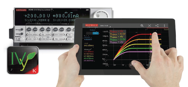
Keithley’s SourceMeter Units, which can act as four instruments in one: a voltage/current source, a voltage/current meter, sweep and lastly, a function generator, provides a perfect solution for such tests. SourceMeters also include a programmable load and can measure I-V characteristics on components from µV to 3 KV and f A to 100 A. A nifty add on is the Ivy app that can download from Google Play for your Android smartphone or tablet that lets you seamlessly perform current-voltage (I-V) characterization on components.
The IVy app is a free download from Google Play for Android devices and makes it easy to check I-V characteristics on components. Here’s a link to a webinar on Characterizing and Validating performance of your Power Semiconductors by our expert.
Once the components have been selected and your prototype is coming together, it’s time for power on. In our next post in this series, we’ll look at low-voltage DC circuit power-on testing and offer tips to ensure you’re able to make an accurate assessment of your design’s performance.